Max Current
Per-motor currents above this value will cause the Sabertooth to apply current limiting.
Min Voltage
Voltages below this value will cause the red error LED to blink and motors to intermittently stop.
Max Voltage
Voltages above this value will cause the red error LED to go on. Regenerative braking will temporarily be replaced by hard braking to keep the voltage from rising further.
Battery
If you have selected Battery Protect mode on the DIP switches, these settings affect the effective Min Voltage and Max Voltage, as well as (if enabled) Automatic Battery Compensation on the Motor Outputs tab. If you are using neither of these features, these settings have no effect.
Pack
The number of cells in your battery pack.
Cell Min
The per-cell minimum voltage.
Cell Max
The per-cell maximum voltage.
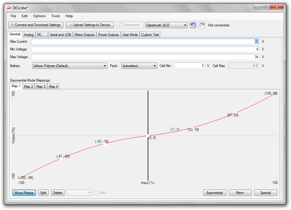
Exponential-Mode Mapping
You can alter the exponential-mode mapping curves to change how the motor driver responds to your input. In Analog and RC modes, this is used when you have selected Exponential response with the DIP switches. For quick customization, try clicking the Exponential button.
The X axis (left-to-right) corresponds to the input, from full reverse on the left to full forward on the right.
The Y axis (bottom-to-top) corresponds to the output, from full reverse on the bottom to full forward on the top.
To give you an idea, notice in the above picture how the curve is flatter near the middle. There is a wide range of input corresponding to a narrow range of output -- changes in input near center cause only small changes in output power. The opposite is true on the sides -- changes in input near the minimum and maximum cause large changes in output power.
The shape of the curve can have a big effect on the feel of the control. Play around and see where it takes you.