Using an LCD as a display would allow you to show many things at once, such as forward, lateral, maximum and average acceleration. However cheap parallel LCDs can be a pain to interface with, and are hard to read if you are driving. Alternatively, $26 will buy you an easy to use Serial LCD with backlight.
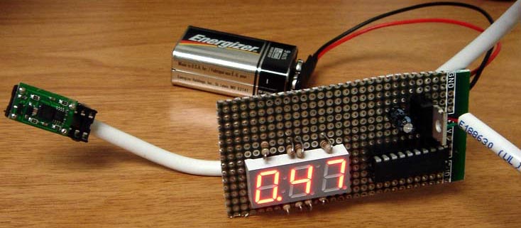
My personal favorite choice was a $2.16 triple digit 7 segment display (Digikey part #160-1544-5-ND). The digits are large and bright and therefore can easily be seen if you are driving. With the 3 digits I had at my disposal, I chose to display acceleration in the form of X.XXg. I could have displayed it as ±X.Xg, but it is pretty obvious when you are in a car whether you are accelerating or braking isn't it? So may as well display extra precision instead.
Schematic
Lite-On's diagrams for the 7 seg display are quite hard to decipher at first, so I have photoshopped them slightly to make them a little bit easier to read. I also cleaned up the PIC pinout to make it specific for this project. For the originals, see the datasheets linked below.
Microcontroller
The 7 seg display requires 11 output pins to drive, and at least 1 analog input to read in acceleration. The most suitable micro I had in my parts box was a PIC16F818. PIC16F818 datasheet
Power
To fit the voltage requirements of the DE-ACCM5G and the PIC, I used a garden variety 7805 regulator. Since many LEDs in the display were being switched on and off very quickly, I used a 22uF capacitor on the 7805's output to keep the power supply stable.
7 seg display
The way I have things hooked up, the 7 segment display only actually ever displays one digit at a time. The displayed digit is chosen by making one of pins A0, A6, A7 high. The actual number to be displayed is then determined by portB, which allows the segments to turn on when a pin goes low. The individual digits are cycled very fast, and persistence of vision creates the illusion of all 3 digits being displayed at once. LTC-4624JR 7 seg display datasheet
Measuring acceleration
The PIC's ADC was set to 10bit resolution, with 5V as the reference voltage. To get a rough estimate, I knew that the 0g on the accelerometer output would be close to 5V / 2 = 2.5V. In 10bit mode, this would correspond to (2.5V / 5V)*(2^10)= 512. At 1g, the voltage would be ~2.812V, which would correspond to (2.812V / 5V)*(2^10)=576. Knowing this helped me write some initial code snippets to display non-calibrated acceleration values.
Calibration
Since this project was designed to display accelerations as small as 10mg, I had to calibrate the microcontroller during development. For example, using a perfect 5.000V reference for the microcontroller's 10 bit ADC with an input of 2.500V would give a 0g value of 512. However, since a 7805's voltage reference is only accurate to within 2%, and no accelerometer is perfect, I found the 0g point to be 510. (See source code).
Source code
The project was written and compiled with CCS PCWH. It is a pricey compiler, but it makes PIC development much easier. Source code and hex file.zip