
DE-ACCM application note
Hacking an alarm clock so that it will enter snooze mode when it experiences a shock.
In this project, we will bypass the mechanical snooze switch on top, and instead turn the alarm clock off in a much more fun way: punching it! Hopefully along the way I will be able to teach you some techniques that are useful in reverse engineering, so you can apply them to future projects.
This project is aimed at intermediate electronics enthusiasts, who have mastered the art of the multimeter and are comfortable with soldering a complex circuit.
This project involves working with a device that connects to mains voltages. The alarm clock I used just so happened to be designed so well that it was impossible to touch any mains voltages inside it. Other alarm clocks may not give you this comfort and will most likely have a different layout inside. Do not attempt this project unless you are 100% sure you know you can do it safely!
Why use an accelerometer?
The DE-ACCM is a good choice for this project because other vibration sensors such as mercury switches or reed switches only provide open or closed switch outputs, whereas the DE-ACCM provides a continuous analog voltage directly proportional to the intensity of the vibrations. For example, a mercury switch might prove to be too insensitive to measure the small vibrations of someone banging on the table, or it might be so sensitive that it activates simply from the vibration of the alarm clock’s speaker. With an accelerometer, you can easily design the circuit to trigger at any amount of vibration you want.
To do this project we must do several things:
Opening her up
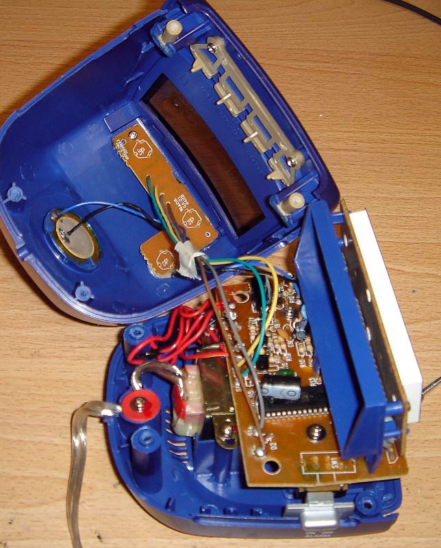
You can see four wires leading to a board that contains the ‘snooze’ and ‘alarm reset’ switches. We will examine those wires very soon. Let us first hunt for a good voltage supply!
Inside the main body of the clock, you can see a small mains transformer that steps 120VAC down to a lower AC voltage. The transformer’s wires lead to an area with a bunch of diodes and capacitors that rectify the AC waveform into DC. But what are all those resistors doing there? What is the deal with those transistors? Things are getting too crowded in that area to easily probe around, so lets try another approach.
Over on the right, you can see a large IC which is clearly responsible for driving all the LEDs on the clock’s screen. Since the chip needs to supply the LEDs with a fair amount of current that could change at any second, it would need a capacitor connected directly in parallel with its power pins. Lo and behold, right next to the chip you will see the largest electrolytic capacitor in the whole circuit. There is a very good chance that the negative side of this cap is connected to the circuit’s ground plane, and the positive side is connected to the filtered positive supply of the circuit.
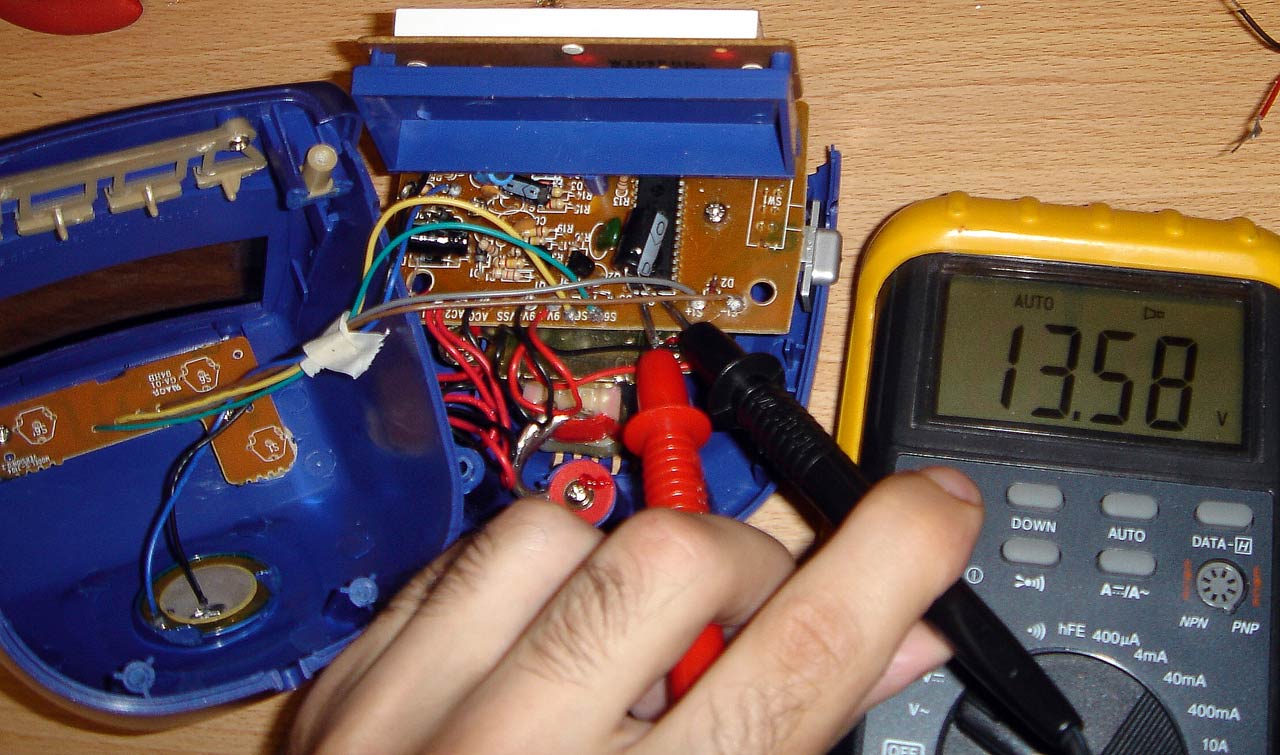
Before powering the clock again, we must double check that no wires are accidentally out of place and shorting each other out as a result of opening the clock up. Once the clock is plugged in again, we can observe the voltage across the big capacitor when the clock is running. The meter reads about 13V DC, and the voltage fluctuates slightly depending on how many LEDs are on in the display at the time – a clear sign that this is definitely the main storage capacitor for the IC. We now know that we have a 13V supply we can work with to power our additional circuit. The negative side of the capacitor is the circuit ground, and we can use it as a reference point when measuring other voltages in the circuit.
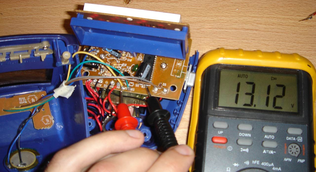
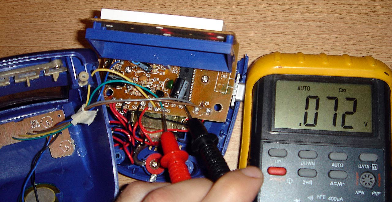
So now we can move on to analyzing the snooze button. After unplugging the clock, we can use the continuity function of our multimeter to see which pair of wires the snooze button is connected to. It turns out that the green and yellow wires are the ones we care about. Power up the clock again, and lets measure what happens on each of those wires when we push the snooze button. On the yellow wire there is 13V when the switch is left alone. When the switch is pushed in, the yellow voltage stays exactly the same. On the green wire, the voltage is 0V. But when we push the switch, the green voltage jumps up to 13V.
From this we can deduce that the snooze button functions like this:

0V on the pin where the green wire connects means the snooze button is released, and 13V on this pin means that the snooze button is being pushed.
We now have everything we need to know to design the circuit. The circuit must operate from a 13V supply. The circuit must output 0V when no vibrations are detected, and output 13V when the accelerometer is vibrating.
When the accelerometer experiences a vibration, it outputs a signal proportional to the vibration levels. A faint tapping on the table the accelerometer is on gives about a 10mV signal. A heavy banging will give 100mV. Directly whacking the accelerometer with your hand will produce 400+mV. We would like to trigger the snooze when the signal is around 100mV or more, and a simple comparator circuit will do this for us nicely.
Circuit diagram
Parts list
| Part name/value | Where to buy | Description |
|---|---|---|
| DE-ACCM | dimensionengineering.com | Accelerometer board |
| LM7805 or equivalent | goldmine-elec.com #G13017 |
5 volt regulator to power the DE-ACCM |
| IC1A LM324 | goldmine-elec.com #G13290 |
We are using just one of the four available op amps on an LM324 as a comparator. An LM311 or any other comparator would work just fine here, but I used an LM324 because I have a huge stock of them and very few LM311s. |
| C1 1uF capacitor | goldmine-elec.com #G14564 digikey.com P5174-ND radioshack.com #272-996 |
High pass filter capacitor. Values from 1uF to 10uF should work just as well |
| R1 100Ω | goldmine-elec.com #G433R digikey.com 100QBK-ND radioshack.com #271-308 |
Lower half of the voltage divider |
| R2 10kΩ | goldmine-elec.com #G475R digikey.com 10KQBK-ND radioshack.com #271-308 |
High pass filter resistor. Values from 5k to 30k should work just as well |
| R3 100Ω | goldmine-elec.com #G433R digikey.com 100QBK-ND radioshack.com #271-308 |
Optional current limiting safety resistor |
| POT1 10kΩ | goldmine-elec.com #G14645 digikey.com AAS14CT-ND radioshack.com #271-1715 |
Potentiometer used as top half of the voltage divider |
| 14 pin chip sockets | goldmine-elec.com #G1234 digikey.com AE8914-ND radioshack.com #276-1999 |
Use them so you don't fry your chips! |
The 13V provided by the clock is beyond the recommended continuous supply rating of a DE-ACCM, so we step it down to 5v using the 7805. No extra capacitor is needed at the output of the 7805 because the DE-ACCM board comes with one built in.
The 1uF capacitor removes any DC bias from the accelerometer output, which eliminates any acceleration due to gravity, leaving us with nothing but an AC vibration signal. The 10k resistor ensures the DC bias of the signal is 0V. This vibration signal is connected to the + input of the comparator.
The voltage divider formed by the 10kΩ pot and the 100Ω resistor will create a reference voltage that can go as low as 50mV. Adjusting the pot will give us a 100mV reference voltage (a good starting point for the sensitivity threshold of the snooze trigger). This reference voltage goes to the – input of the comparator.
When there is no vibration signal, the reference voltage of ~100mV is higher, so the output of the comparator stays at 0V. When there is a sudden shock that causes the vibration signal to jump higher than the reference voltage, the output of the comparator jumps up to 13V, which is exactly the snooze signal that we want.

After building the circuit, it is a good idea to test if it functions correctly with 13v coming from a bench supply before trying it in the actual clock.
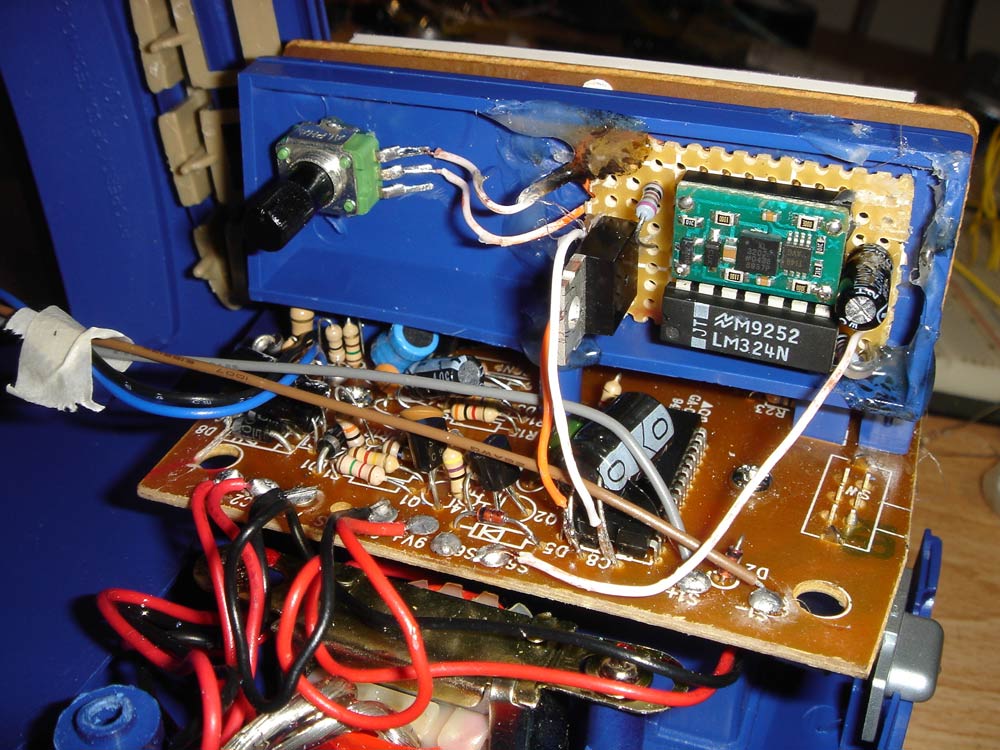
The final step is to hot glue our little circuit board into place, and to solder the power wires across the capacitor, and the snooze signal wire to where the green wire used to be.
Power it up, and adjust the pot to make the alarm deactivate at whatever threshold of pain you wish your alarm clock to endure.
Greatest hits video (wmv 1.8mb) Greatest hits video (mpg 2.6mb)
Back to Dimension Engineering